
Core Content
1. Construction of a Simple Transformer
Definition:
A transformer is a device used to increase or decrease the voltage of an alternating current (a.c.) supply.
Main parts of a transformer:
- Primary Coil: The coil connected to the input voltage Vp.
- Secondary Coil: The coil connected to the output voltage Vs.
- Soft Iron Core: Links the two coils and strengthens the magnetic field.
Key Points:
- The coils are insulated (no direct electrical connection).
- Only a.c. can be transformed, not d.c. (direct current).
- The soft iron core is easily magnetized and demagnetized, improving efficiency.
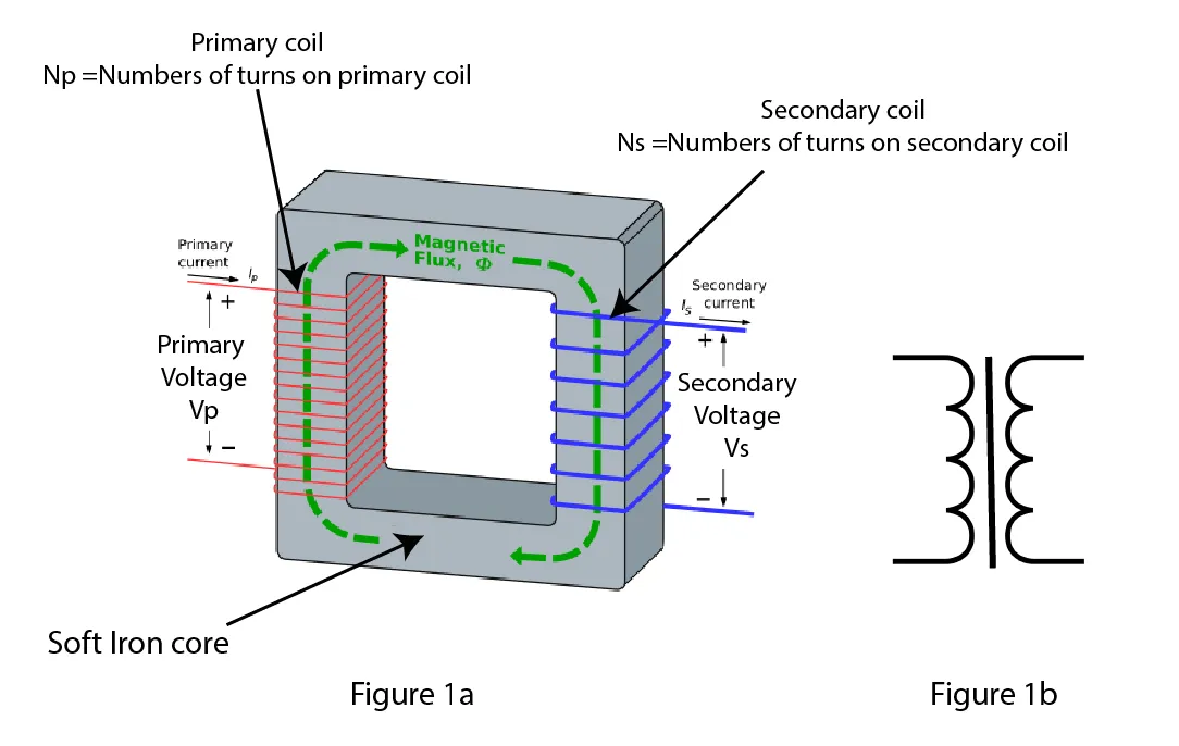
Figure 1a: The structure of a transformer. This is a step-down transformer because there are more turns on the primary coil than on the secondary. If the connections to it were reversed, it would be a step-down transformer. Figure 1b: The circuit symbol for a transformer shows the two coils with the core between them.
2. Terms to Know
- Primary coil (input side): where the original voltage is applied.
- Secondary coil (output side): where the transformed voltage is taken.
- Step-up Transformer: increases voltage (more turns on secondary coil than primary coil).
- Step-down Transformer: decreases voltage (fewer turns on secondary coil than primary coil).
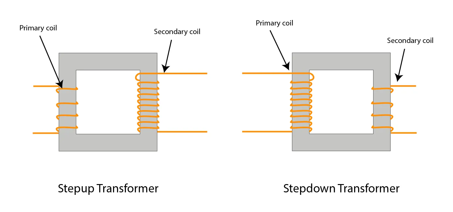
Figure 2: Step-up and step-down transformer comparison (showing coil turns).
3. Transformer Equation
The relationship between voltage and number of turns:
Where:
- Vp = Voltage across primary coil
- Vs = Voltage across secondary coil
- Np = Number of turns on primary coil
- Ns = Number of turns on secondary coil
Note:
- If Ns > Np → Step-up transformer (voltage increases).
- If Ns < Np → Step-down transformer (voltage decreases).
- When voltage increases, current decreases (and vice versa).
4. Use of Transformers in High-Voltage Transmission
- Power stations generate electricity at around 20 kV.
- Step-up transformers raise the voltage to about 320 kV for transmission across long distances.
- Step-down transformers near towns and cities reduce the voltage to lower, safer levels for homes and factories.

Figure 3: In a national grid, voltages are increased to reduce energy losses, then reduced to a relatively safe level.
5. Advantages of High-Voltage Transmission
- Less energy loss: High voltage means low current, so there is less heating effect in the cables.
- Cheaper infrastructure: Lower current allows the use of thinner and cheaper cables.
Summary Table:
| Advantage | Explanation |
|---|---|
| Less energy lost as heat | Low current reduces heating in wires |
| Thinner, cheaper cables | Lower current means less thick cables needed |
Additional Important Points to Remember:
- Transformers are highly efficient (up to 99.9% efficient).
- Without using high voltages, about 10% energy could be wasted before reaching homes.
- The iron core can become laminated (thin sheets) to further reduce energy losses due to eddy currents (you can mention this for extra detail if needed).
Supplement Content
6. Principle of Operation of a Transformer
- Alternating current (AC) flows in the primary coil → creates an alternating magnetic field.
- This magnetic field is carried through the soft iron core to the secondary coil.
- The changing magnetic field induces an alternating voltage in the secondary coil (Electromagnetic Induction).
✅ Key Points:
- AC only — transformers do not work with direct current (DC).
- Soft iron core improves efficiency (easy magnetization/demagnetization).
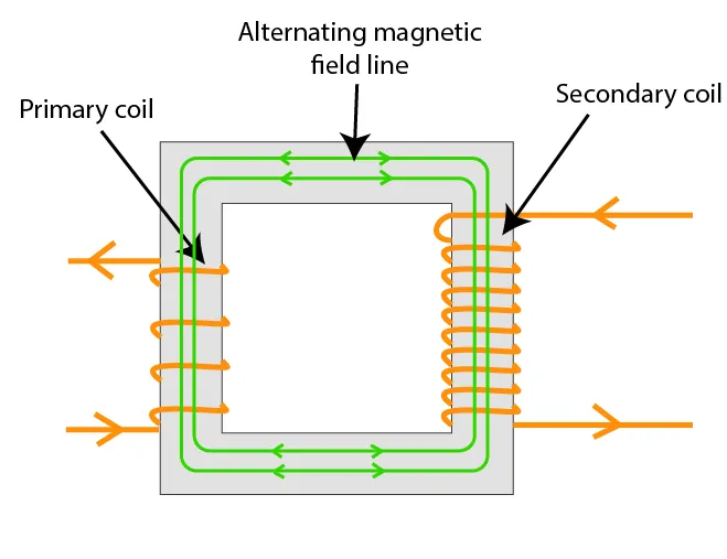
Figure 4: The a.c. in the primary coil produces a varying magnetic field in the core. This induces a varying current in the secondary coil.
7. Efficiency in Transformers
Assuming 100% efficiency:
Where:
- Ip = current in primary coil
- Vp = voltage across primary coil
- Is = current in secondary coil
- Vs = voltage across secondary coil
✅ Key Point:
Power input = Power output (if no losses).
8. Power Losses in Cables
When electricity flows through cables:
- Some energy is lost as heat due to resistance.
Power loss is calculated by:
Where:
- P = power loss
- I = current
- R = resistance of the cable
✅ Key Points:
- Power loss depends on current squared.
- Reducing current (by increasing voltage) greatly reduces energy loss.
Examples:
- Double current → 4× losses.
- Triple current → 9× losses.
- Halving current → ¼ losses.
Summary of Key Equations
| Concept | Equation |
|---|---|
| Turns and Voltage Ratio | Vp/Vs = Np/Ns |
| Transformer Efficiency | IpVp = IsVs |
| Power Loss in Cables | P = I2R |