Series Circuits

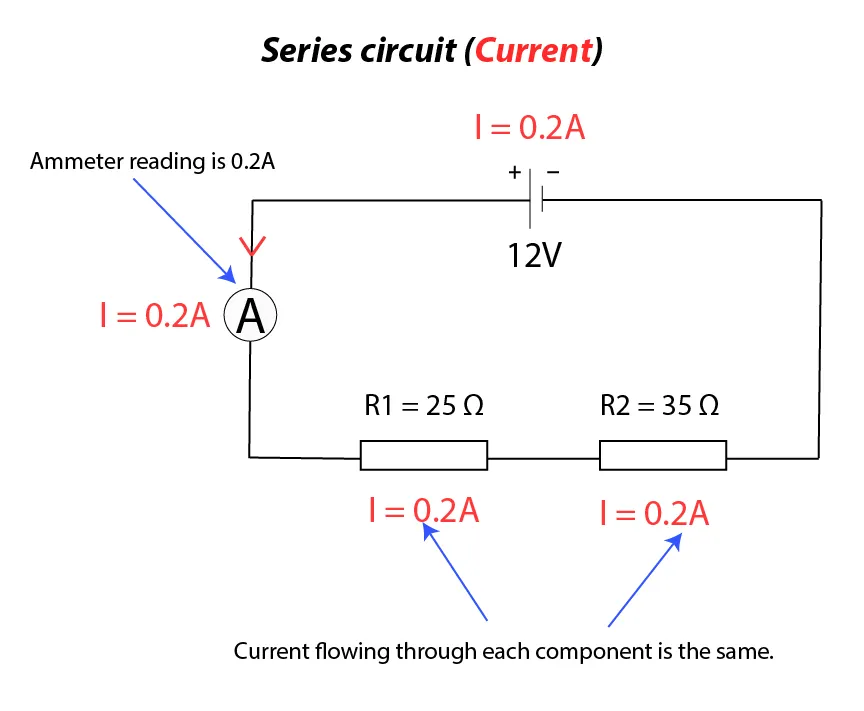
In a series circuit, components are connected end-to-end, creating a single path for the current to flow. The key characteristics of series circuits are:

  • The current (\( I \)) is the same at every point in the circuit.
  • The total resistance (\(R_f\)) is the sum of the individual resistances: \[ R_f = R_1 + R_2 + R_3 \]
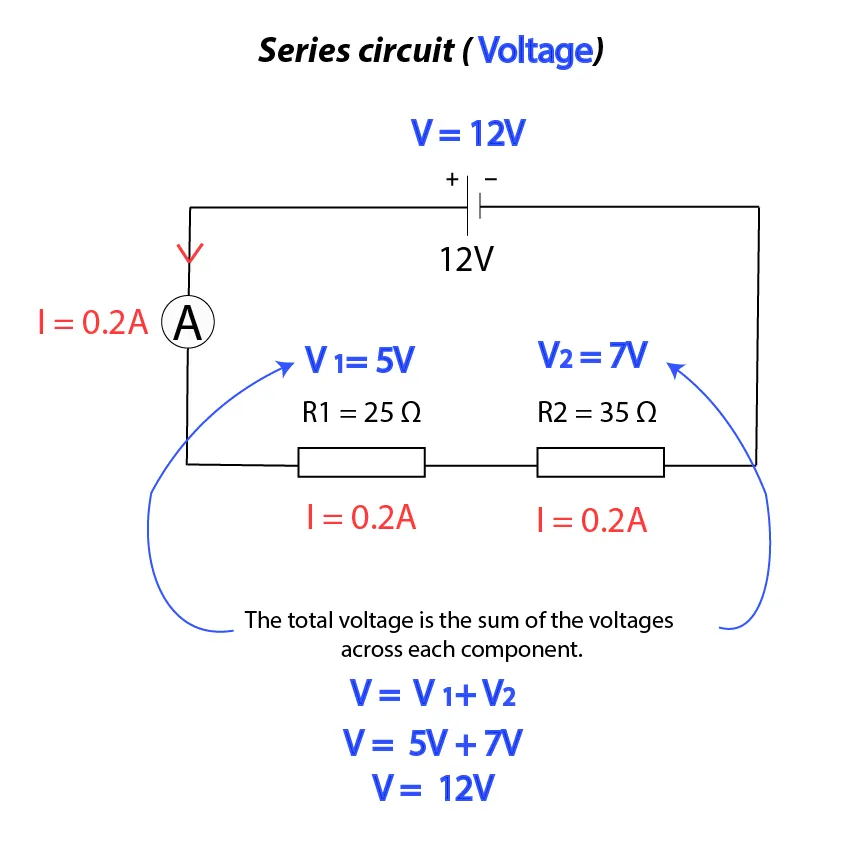
  • The potential difference across the entire circuit is the sum of the p.d.s across each component: \[ V = V_1 + V_2 + V_3 \]

  • When multiple cells are connected in series, their total e.m.f. is the sum of each cell's e.m.f. For example, two cells with e.m.f.s of 2.0V each will have a combined e.m.f. of 4.0V.
Resistors in Series Resistors in Series

Parallel Circuits

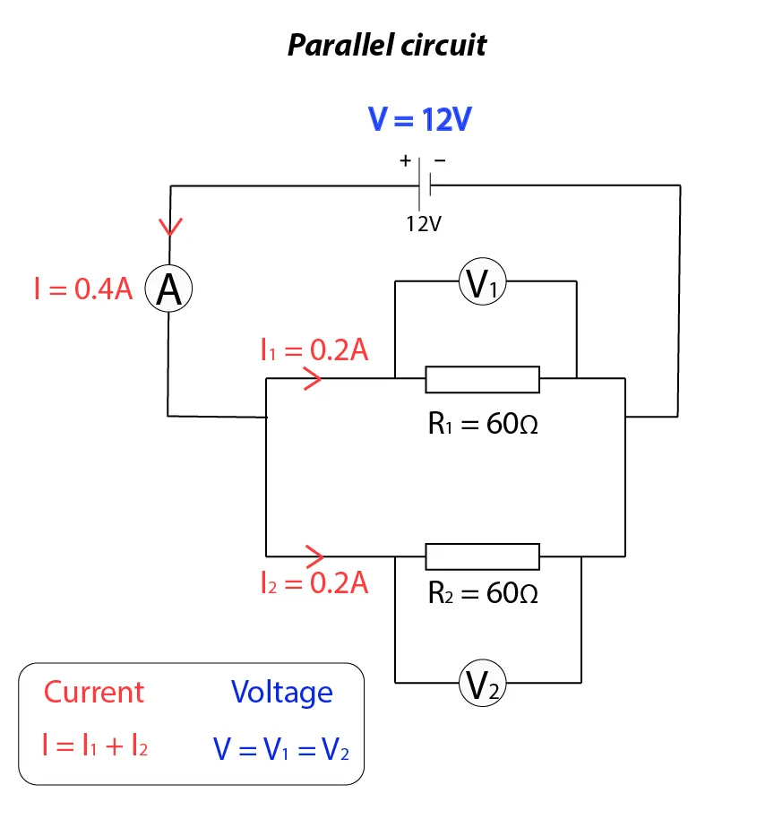
In a parallel circuit, components are connected across common points, providing multiple paths for the current to flow. The key characteristics of parallel circuits are:

  • The current from the power source is divided among the branches, so the total current is greater than the current in each branch.
  • The combined resistance of components in parallel is less than the smallest individual resistance.
  • The sum of the currents entering a junction equals the sum of the currents leaving the junction: \[ I_1 = I_2 + I_3 \]

  • The potential difference across each branch is the same: \[ V_1 = V_2 \]

  • The total resistance \(R_f\) of two resistors in parallel is calculated using: \[ \frac{1}{R_f} = \frac{1}{R_1} + \frac{1}{R_2} \]

Resistors in Parallel

Current is the flow of electrons, and electrons cannot be created or destroyed. This means the number of electrons flowing per second must be the same at every point in the circuit. This principle explains why the sum of the currents entering a junction equals the sum of the currents leaving the junction. It also explains why the current in a series circuit is the same at every point.

In lighting circuits, lamps are connected in parallel for several reasons:

  • Each lamp receives the same potential difference, ensuring consistent brightness.
  • Lamps can be controlled independently, allowing individual switching.
  • If one lamp fails, the others continue to operate normally.

Sample Questions

Question 1: In a series circuit, \( R_1 = 5 \Omega \) and \( R_2 = 7 \Omega \).

a) Calculate the total resistance of \( R_1 \) and \( R_2 \).

b) The current through \( R_1 \) is 2.0 A. State the current through \( R_2 \).

c) Calculate the potential differences \( V_1 \) and \( V_2 \).

d) The potential difference across all three resistors is 24 V. Calculate the value of \( V_3 \) and hence the resistance of \( R_3 \).

Answer:

a) Total resistance = \( 5 + 7 = 12 \Omega \).

b) Current through \( R_2 \) = current through \( R_1 \) = 2.0 A.

c) \( V_1 = I \times R_1 = 2.0 \times 5 = 10 \, \text{V} \)

\( V_2 = I \times R_2 = 2.0 \times 7 = 14 \, \text{V} \)

d) Supply potential difference = sum of p.d.s of rest of circuit = 24 V

\( 24 = V_1 + V_2 + V_3 \)

\( 24 = 10 + 14 + V_3 \)

\( V_3 = 24 - (10 + 14) = 0 \, \text{V} \)

\( R_3 = \frac{V_3}{I} = \frac{0}{2.0} = 0 \Omega \)

Question 2: In a parallel circuit, \( R_1 = 6 \Omega \), \( R_2 = 4 \Omega \), \( I_1 = 3.0 \, \text{A} \), and \( I_2 = 1.5 \, \text{A} \).

a) Calculate the current \( I_3 \).

b) Calculate the total resistance of \( R_1 \) and \( R_2 \).

c) Calculate the e.m.f. of the power supply.

Answer:

a) Current \( I_3 = I_1 - I_2 = 3.0 - 1.5 = 1.5 \, \text{A} \).

b) \( \frac{1}{R_f} = \frac{1}{R_1} + \frac{1}{R_2} = \frac{1}{6} + \frac{1}{4} = \frac{5}{12} \), \( R_f = 2.4 \, \Omega \).

c) e.m.f. = \( 1.5 \times 2.4 = 3.6 \, \text{V} \).

Revision Activity

Create a table summarizing the key differences between series and parallel circuits.

Comparison of Series and Parallel Circuits

Feature Series Circuit Parallel Circuit
Current The same current flows through all components. The total current is divided among the branches.
Potential Difference (Voltage) The total voltage is the sum of the voltages across each component. The voltage is the same across all branches.
Resistance The total resistance is the sum of individual resistances: \[ R_f = R_1 + R_2 + R_3 \] The total resistance is less than the smallest individual resistance: \[ \frac{1}{R_f} = \frac{1}{R_1} + \frac{1}{R_2} \]
Effect of a Fault If one component fails, the entire circuit stops working. If one component fails, the other branches continue to work.
Use in Lighting Circuits Not commonly used for lighting circuits. Lamps are connected in parallel to ensure consistent brightness and independent operation.
Current at Junctions Not applicable (no junctions in series circuits). The sum of currents entering a junction equals the sum of currents leaving: \[ I_1 = I_2 + I_3 \]
Combined E.M.F. The combined e.m.f. is the sum of individual e.m.f.s: \[ E_f = E_1 + E_2 \] Not applicable (e.m.f. is the same across all branches).

Additional Questions and Answers

Core Questions (Series Circuits)

Question 3: In a series circuit, \( R_1 = 8 \Omega \) and \( R_2 = 12 \Omega \).

a) Calculate the total resistance of \( R_1 \) and \( R_2 \).

b) The current through \( R_1 \) is 1.2 A. State the current through \( R_2 \).

c) Calculate the potential differences \( V_1 \) and \( V_2 \).

Answer:

a) Total resistance = \( 8 + 12 = 20 \Omega \).

b) Current through \( R_2 \) = current through \( R_1 \) = 1.2 A.

c) \( V_1 = I \times R_1 = 1.2 \times 8 = 9.6 \, \text{V} \)

\( V_2 = I \times R_2 = 1.2 \times 12 = 14.4 \, \text{V} \)

Question 4: In a series circuit, \( R_1 = 10 \Omega \), \( R_2 = 15 \Omega \), and the total potential difference across the circuit is 50 V.

a) Calculate the total resistance of the circuit.

b) Calculate the current flowing through the circuit.

c) Calculate the potential difference across \( R_1 \).

Answer:

a) Total resistance = \( 10 + 15 = 25 \Omega \).

b) Current = \( \frac{V}{R} = \frac{50}{25} = 2.0 \, \text{A} \).

c) \( V_1 = I \times R_1 = 2.0 \times 10 = 20 \, \text{V} \).

Extended Questions (Parallel Circuits)

Question 5: In a parallel circuit, \( R_1 = 6 \Omega \) and \( R_2 = 9 \Omega \). The total current from the power supply is 5.0 A.

a) Calculate the total resistance of \( R_1 \) and \( R_2 \).

b) Calculate the current through each resistor (\( I_1 \) and \( I_2 \)).

c) Calculate the potential difference across each resistor.

Answer:

a) \( \frac{1}{R_f} = \frac{1}{6} + \frac{1}{9} = \frac{5}{18} \), \( R_f = 3.6 \, \Omega \).

b) The potential difference across each resistor is the same. First, calculate the p.d.: \[ V = I \times R_f = 5.0 \times 3.6 = 18 \, \text{V} \] Then, calculate the currents: \[ I_1 = \frac{V}{R_1} = \frac{18}{6} = 3.0 \, \text{A} \] \[ I_2 = \frac{V}{R_2} = \frac{18}{9} = 2.0 \, \text{A} \]

c) The potential difference across each resistor is 18 V.

Question 6: In a parallel circuit, \( R_1 = 4 \Omega \), \( R_2 = 6 \Omega \), and the current through \( R_1 \) is 3.0 A.

a) Calculate the potential difference across \( R_1 \).

b) Calculate the current through \( R_2 \).

c) Calculate the total current from the power supply.

Answer:

a) \( V_1 = I_1 \times R_1 = 3.0 \times 4 = 12 \, \text{V} \).

b) Since the p.d. is the same across both resistors: \[ I_2 = \frac{V}{R_2} = \frac{12}{6} = 2.0 \, \text{A} \]

c) Total current = \( I_1 + I_2 = 3.0 + 2.0 = 5.0 \, \text{A} \).

Leave a Reply

Your email address will not be published. Required fields are marked *

error: Content is protected !!