Resistance is the opposition to the flow of electric current. It is measured in ohms (Ω).
Formula:
where: R = resistance (Ω) V = potential difference (volts) I = current (amperes)
Ohm’s Definition: One ohm is the resistance when 1 volt causes 1 ampere of current to flow. $$1Ω=1{{V}\over{A}}$$
How Resistance Affects Circuits
A low resistance allows more current to flow, while high resistance reduces current.
Resistance depends on the shape and material of the conductor:
Longer wires have higher resistance.
Wires with larger diameters have lower resistance.
Example
A simple circuit consists of a cell, an ammeter, a voltmeter, and a resistor. The ammeter detects a current of 0.04A, and the voltmeter detects a voltage of 10V. Calculate the resistance of the resistor.
Answer:
use of Equation
Check what you have given with
Current = 0.04A
Voltage = 10V
substitute values into equation and rewrite the equation
R = 250Ω
Measuring Resistance
Using a Circuit to Measure Resistance
Components required:
Variable Power supply
Ammeter (to measure current)
Voltmeter (to measure potential difference)
Steps:
Connect the resistor in the circuit with an ammeter in series and a voltmeter across the resistor.
Record the readings of the current and voltage.
Use R=V/I to calculate resistance.
Important Connections
Ammeters are connected in series.
Voltmeters are connected in parallel across the component.
As you increase the voltage across a fixed resistor, the current flowing through it will increase proportionally.
Think of it like a water pipe. The resistance of the pipe is fixed. If you increase the water pressure (voltage), more water will flow through the pipe (current).
Typical results for an experimental measurement of resistance.
Factors Affecting Resistance
Effect of Length and Thickness
Resistance increases with the length of the wire.
Resistance decreases as the diameter of the wire increases.
Think of electricity flowing like water through a pipe. A long, narrow pipe slows the flow more than a short, wide pipe.
A metallic wire
Experiment:
Investigating Resistance
Aim: To investigate how the length and thickness of a wire affect its resistance.
Apparatus:
Cell
Insulated wires with crocodile clips
Meter ruler
Resistance wires (thin and thick)
Heatproof mat
Ammeter and voltmeter
Procedure:
Secure the resistance wire along the meter ruler using masking tape.
Connect the circuit with the ammeter in series and voltmeter in parallel across the resistance wire.
Attach one crocodile clip at the 0 cm mark of the ruler.
Attach the second clip at intervals of 10 cm along the wire.
Record the voltage (V) and current (I) at each interval.
Calculate resistance (R=V/I ) for each length.
Repeat steps 3–6 with a thicker wire.
Plot a graph of resistance against the length of the wire for both thin and thick wires.
Conclusion:
Resistance increases with wire length.
Resistance decreases with greater wire diameter.
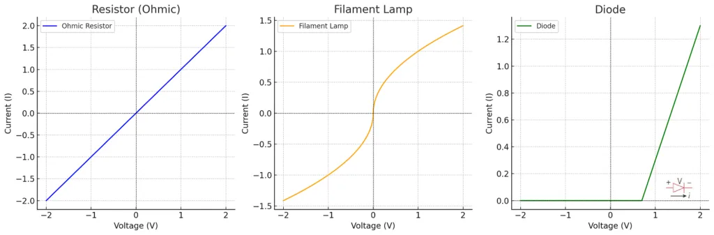
Sketch and Explain the Current–Voltage Graphs for a Resistor, Filament Lamp, and Diode
Current–Voltage Characteristics
Resistor (Ohmic Resistor):
The graph is a straight line passing through the origin (Figure: Current–voltage graph for a resistor).
Current (I) is directly proportional to potential difference (V) as per I=VR.
A resistor with this characteristic is called an ohmic resistor. Doubling the voltage doubles the current.
Filament Lamp:
At low voltages, the graph is initially straight, but it curves at higher voltages (Figure: Current–voltage graph for a filament lamp).
Current increases more slowly at higher voltages due to an increase in resistance caused by the filament heating up.
When the filament heats up, collisions between electrons and the metal lattice increase, converting kinetic energy into internal energy. This increases resistance.
Diode:
The graph is not symmetrical and allows current to flow only in one direction (Figure: Current–voltage graph for a diode).
A diode behaves as an insulator below a threshold voltage (e.g., 0.7 V for a silicon diode). Above this, it conducts.
The arrow in the diode’s symbol indicates the direction of current flow.
Relationship Between Resistance, Length, and Cross-Sectional Area of a Wire
Proportional to Length:
Resistance R ∝ length (L). Doubling the length doubles the resistance.
R ∝ length (L)
Inversely Proportional to Cross-Sectional Area:
Resistance R ∝ 1/area (A). Doubling the cross-sectional area of a conductor quarters (1/4) its resistance.
Examples 01:
A wire of 4.0 m length with resistance 200 Ω:
Halving the length to 2.0 m reduces resistance to 100 Ω.
Doubling the area further reduces it to 50 Ω.
Examples 02:
A 2.0 metre length of wire has a resistance of 4.0 Ω.
What is the resistance of a piece of the same wire of length 20.0 metres?
What is the resistance of a 4.0 metre wire with half the cross-sectional area, made of the same material?
What is the resistance of a 6.0 metre wire with one quater the cross-sectionalarea, made of the same material?
What is the resistance of a 8.0 metre wire with double the cross-sectionalarea, made of the same material?
Answer:
for L = 2m , R = 4Ω
When length increase resistance also increases as length is proportional to the resistance
Therefore, 20m/2m =10,
10 x 4 = 40Ω
When area decreases resistance increases
half the area mean it has been decreased by 4 times.
Therefore, 4m x 4 = 16Ω
6m x 16 = 96Ω
When cross sectional area increases resistance decreases