3.2 Light
3.2.1 Reflection of Light
Normal: A line perpendicular to the surface at the point of incidence.
Angle of Incidence (i): The angle between the incident ray and the normal.
Angle of Reflection (r): The angle between the reflected ray and the normal.

Image Formation by a Plane Mirror:
- The image is virtual (cannot be projected).
- The image is the same size as the object.
- The distance from the mirror to the image is equal to the distance from the mirror to the object.
Law of Reflection:
The angle of incidence is equal to the angle of reflection (i = r).
Supplement :
Plane Mirror Construction:
- Use ray diagrams to represent the reflection of light from plane mirrors.
- Measure angles of incidence and reflection to verify the law of reflection.

Diagram above showing the formation of an image in a mirror by the reflection of light.
- Light from the object hits the mirror and it reflects (i = r)
- To an observer the reflected ray seems to have come from the mirror’s right side
- The reflected ray can be traced back in this directions, forming a virtual ray
- This can be repeated for another ray travelling in a slightly different direction
- An image of the object will appear where these two virtual rays cross
- The type of image formed in the mirror is called a virtual image
- A virtual image is formed by the divergence of rays from the image, and cannot be projected onto a piece of paper (because the rays don’t actually go through the image)
3.2.2 Refraction of Light
Normal, Angle of Incidence, and Angle of Refraction:
- Angle of Incidence (i): Angle between the incident ray and the normal at the boundary.
- Angle of Refraction (r): Angle between the refracted ray and the normal in the second medium.
When a ray of light passes from one medium to another, it bends. This bending of light is called “refraction“.
Refraction Experiment:

The passage of light through parallel-sided transparent material
- When light travels from a less dense material to a more dense material (e.g. from air to water), the light ray bends towards the normal. (Angle of incidence > angle of refraction)
- When light travels from a more dense material to a less dense material (e.g. from water to air), the light ray bends away from the normal. (Angle of refraction > angle of incidence)
When a ray of light enters from less dense (Air) to denser (Glass) medium, it is bent towards the normal.

When a ray of light enters from denser (Glass) to less dense (Air) medium, it is bent away from the normal.

“Highly dense medium”
If light travels slower in a medium than another medium, then this medium is described as “highly dense medium” than the other.
“Less dense medium”
If light travels faster in a medium than another medium, then this medium is called less denser than the other.

Critical Angle:
-
The angle of incidence in the denser medium for which the angle of refraction in the less dense medium is 90°. and the refracted ray travels along the surface.

Internal and Total Internal Reflection:
- When light is moving from a denser medium towards a less dense medium, most of the light is refracted, but a small amount of it can be internally reflected
- However, if the angle of the light is great enough then instead of being refracted, ALL of the light is reflected
- This is called Total Internal reflection and happens when the angle of the incident ray is greater than the critical angle for that material

Total Internal Reflection Examples
Total internal reflection is used to reflect light along optical fibers
When light enters one end of an optical fibre cable, it undergoes total internal reflection until it reaches the end of the cable.
When light strikes the wall of the optical fibre, the angle of incidence is greater than the critical angle and therefore, total internal reflection occurs. (there is very little loss of energy). The light considered ‘trapped’ in the optical fibre and can travel long distances, even if the fibre is bent.

Uses of optical fibre
- Long distance communication (telecommunication) Companies to transmit telephone signals, Internet communication and cable television signals.
- Optical fibres are often used in medical procedures. One example is to use an endoscope to illuminate and visualise areas that couldn’t normally be seen. Doctors used to have to operate to see what the problem was.
Supplement:
1. Refractive Index (n):
Equation for Refractive Index:
$$n={{sin(i)}\over{sin(r)}}$$
Explanation: This equation relates the refractive index (n) of a material to the angle of incidence (i) and the angle of refraction (r). This comes from Snell’s Law.
-
i = Angle of incidence (the angle between the incident ray and the normal at the boundary).
-
r = Angle of refraction (the angle between the refracted ray and the normal).
-
n = Refractive index of the material
Example 01:
A light ray strikes the surface of a glass block at an angle of incidence of 30°. If the angle of refraction inside the glass is 19°, calculate the refractive index of glass.
Given:
i = 30°
r = 19°
Using the formula: $$n={{sin(i)}\over{sin(r)}}$$
Substituting values: $$n={{sin(30°)}\over{sin(19°)}}$$
Calculating:
sin30° = 0.5
sin19° ≈ 0.325
So, $$n={{0.5}\over{0.325}}\;=\;1.54$$
The refractive index of glass is approximately 1.54.
2. Equation for Critical Angle:
Equation for Refractive Index:
$$n={{1}\over{sin(c)}}$$
Explanation: This equation relates the refractive index (n) of a material to its critical angle (c), which is the angle of incidence at which light is refracted along the boundary (90° to the normal) and beyond which total internal reflection occurs.
-
c = Critical angle (the angle of incidence where the refracted angle is 90°).
-
n = Refractive index of the material
Example 02:
The critical angle for a certain type of glass is 42°. Calculate the refractive index of the glass.
Given:
c = 42°
Using the formula: $$n={{1}\over{sin(c)}}$$
Substituting values: $$n={{1}\over{sin(42)}}$$
Calculating:
sin42° = 0.669
So, $$n={{1}\over{0.669}}=\;1.49$$
The refractive index of glass is approximately 1.49.
3. Equation for Refractive Index (Speed of Light):
Equation for Refractive Index:
$$n={{Speed\;of\;light\;in\;air}\over{Speed\;of\;light\;in\;the\;medium}}$$
Explanation: This equation shows that the refractive index (n) is the ratio of the speed of light in a vacuum or air to the speed of light in a material (such as glass or water).
-
Speed of light in air (approximately 3.0×\( 10^8\)m/s)
-
n = Refractive index of the material
Example 03:
The speed of light in water is 2.25×\( 10^8\) m/s. Calculate the refractive index of water.
Given:
Speed in air= 3.0×\( 10^8\)m/s
Speed in water= 2.25×\( 10^8\) m/s
Using the formula: $$n={{Speed\;of\;light\;in\;air}\over{Speed\;of\;light\;in\;the\;medium}}$$
Substituting values:
$$n={{3.0 \times 10^8m/s}\over{2.25 \times 10^8 m/s}}=\;1.33$$
So,
The refractive index of water is 1.33.
Summary of Refractive Index Equations:
- \(n={{sin(i)}\over{sin(r)}}\) (Snell’s Law)
- \(n={{1}\over{sin(c)}}\) (Critical Angle)
- \(n={{Speed\;of\;light\;in\;air}\over{Speed\;of\;light\;in\;the\;medium}}\)
3.2.3 Thin Lenses
Action of Thin Converging and Diverging Lenses:
- Converging lens: Bends parallel rays of light towards a single point (focus). A converging (or convex) lens is thickest in the centre and bends light inwards (E.g: magnifying glass)

- Diverging lens: Spreads parallel rays of light away from a point (virtual focus).

Key Terms:
- Focal Length (f): The distance between the lens and its focal point.
- Principal Axis: A straight line passing through the center of the lens and its focal points.
- Principal Focus (Focal Point): The point where rays parallel to the principal axis converge (for a converging lens) or appear to diverge from (for a diverging lens).
Ray Diagrams for Converging Lens (Real Image):
1. Object placed between one and two focal lengths from the lens, the image is:
- inverted
- magnified
- real

2. Object that is placed more than twice the focal length from the lens, the image is:
- inverted
- diminished
- real

3. Object is placed at exactly twice the focal length (2f) from the lens, the image is:
- Real
- Same size as the object
- Inverted

Virtual Image:
- Formed when diverging rays are extended backward to meet. It cannot be captured on a screen.
Supplement:
4. Object is placed at a distance less than the focal length. The image is:
- upright
- magnified
- virtual

Above shows a ray diagram for an object placed less than one focal length from a convex lens
Only the person using the magnifying glass can see the image. The image cannot be projected onto a screen because it is a virtual image. Only a real image can be projected onto a screen
Magnifying Glass:
- A converging lens is used as a magnifying glass by placing the object closer to the lens than its focal length, producing a large virtual image.

Lens Use in Vision Correction:
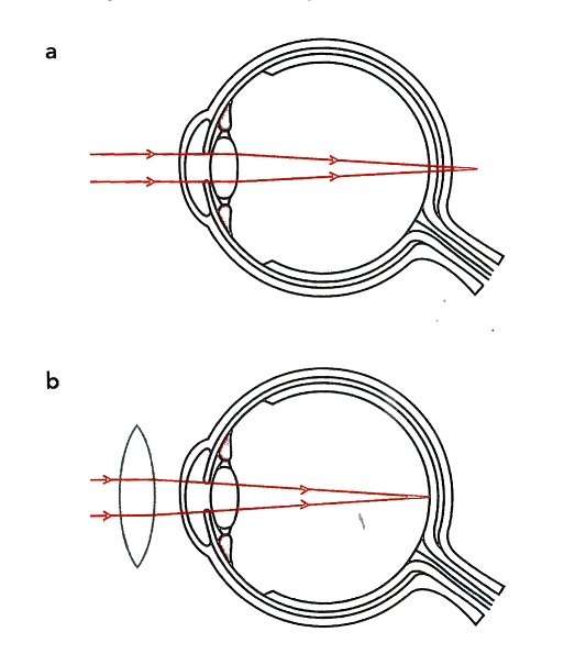
1. Long sight
Converging lenses correct long-sightedness (hyperopia) by converging light onto the retina.
- A long-sighted person has the opposite problem to short-sightedness. A long-sighted eye can focus on distant objects but not on close ones. This may happen because the eyeball is too short or the lens cannot become strong enough to converge light rays from a nearby object to form an image on the retina. A converging (convex) lens helps by bending the light rays inward, allowing the eye’s lens to focus and form a clear image of close objects.

Diagram “b” : A converging lens works with the lens in the eye to form an image on the retina.
2. Short sight
Diverging lenses correct short-sightedness (myopia) by spreading light before it reaches the retina.
- A person with short-sightedness can see close objects clearly but cannot focus on distant objects. The image forms in front of the retina, usually because the eyeball is slightly too long, causing the light rays to meet before reaching the retina. A diverging (concave) lens is used to spread the light rays outward, allowing the eye’s lens to focus and form a clear image of distant objects.

Diagram “b”: Using a diverging lens to help the lens in the eye to form an image on the retina.
3.2.4 Dispersion of Light Thin Lenses
When light enters from less dense to a denser medium, for instance air to glass, it slows down (refracts), which causes it to bend.
White light is made up of seven colours. Each colour is refracted by a different amount in glass.

If a beam of light falls on a glass prism, it is dispersed into a spectrum of the seven colours.
The prism refracts each color by a different amount
- Red light is deviated or bent least by a prism.
- Violet light is deviated most by a prism.
The different colours of light all have different wavelengths
- Red has the largest wavelength (deviated least by a prism)
- Violet has the shortest wavelength (deviated most by a prism)

spectrum: (plural: spectra) waves, or colours, of light, separated out in order according to their wavelengths
dispersion: the separation of different wavelengths of light because they are refracted through different angles
Supplement:
Monochromatic Light:
Light that consists of only one frequency (or one color).
- Light of a single color is not dispersed by a prism. It is refracted, meaning it changes direction, but it does not split into a spectrum. This happens because it is light of just one color. Such light is called monochromatic (mono = one, chromatic = color). Monochromatic light has only one frequency.

AMAZİNG NOTES!!!
It above my understanding!
life saviour indeed